Surge Impedance Loading in Transmission Line
Surge impedance is the characteristic impedance of a loss-less line. When a transmission line is terminated with a surge impedance, it can be said to be surge impedance loading. Further, during this operation, the line operates at unity power factor. The mathematical expression for surge impedance loading (SIL) in transmission line is:
$SIL = \frac{V_{RL}^2}{Z_o} MW$
Here, $V_{RL}$ is the receiving end voltage of the line in kV, and $Z_o$ is the surge impedance of the line.
In this article, we will discuss how one can derive the expression of surge impedance loading for the transmission line. The mathematical derivation of the expression for SIL begins with the ABCD parameters of the transmission line. Whereas determining the ABCD parameters requires the modelling of the transmission line.
Mathematical Derivation of Surge Impedance Loading in Transmission Line
After modelling the long transmission line, one can write the performance parameters in terms of ABCD constants as
$\begin{equation} \begin{bmatrix} V_S \\ I_S \end{bmatrix} = \begin{bmatrix} A & B \\ C & D \end{bmatrix} \begin{bmatrix} V_R \\ I_R \end{bmatrix} \end{equation}$ ….(1)
Here, $A=cosh \gamma l$
$B =Z_c: sinh \gamma l$
$C=\frac{1}{Z_c}:sinh \gamma l$
$D=A=cosh \gamma l$
Propagation Constant (γ)
The term $\gamma$ is a propagation constant. Here, the term propagation constant determines the behaviour of an electromagnetic wave in a transmission line. The mathematical expression for $\gamma$ is
$\gamma = \alpha + j \beta$
The $\alpha$ is the attenuation constant. α causes signal amplitude to decrease along the line. Whereas, $\beta$ is the phase constant. The phase constant $\beta$ determines the sinusoidal amplitude per phase of the signal along the line.
For a loss-less transmission line, the value of $\alpha$ is zero. This means that no attenuation of the signal takes place.
Mathematical Explanation
Now, let’s consider a transmission line of length $l$ terminated with a surge or characteristic impedance ($Z_o$). $x$ is the distance from the receiving end side of the line, i.e., for the receiving end, $x=0$ and for the sending end, $x=l$.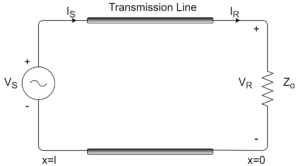 From relation (1),
\[
\begin{aligned}V(x) &= A(x) V_R + B(x) I_R\\
&= cos(beta x) V_R + j Z_0 sin(\beta x) I_R
\end{aligned}
\]
\[
\begin{aligned}
I(x) &= C(x) V_R + D(x) I_R\\
&= \frac{j sin(\beta x)}{Z_0} + cos(\beta x) I_R
\end{aligned}
\]
In the above expression, $V(x)$ is the voltage at $x$ distance away from the receiving end. $I(x)$ is current at $x$ distance away from the receiving end. $V_R$ and $I_R$ is the voltage and current at the receiving ends, respectively.
For a line that is terminated by $Z_o$,
$I_R = \frac{V_R}{Z_o}$
So,
\[
\begin{aligned}
V(x) &= cos(\beta x) V_R + j Z_0 sin(\beta x) I_R\\
&= cos(\beta x) V_R + j Z_0 sin(\beta x) \frac{V_R}{Z_0}\\
&= e^{j\beta x} V_R , \text{Volts}
\end{aligned}
\]
\[
|V(x)| = |V_R| , \text{Volts}
\]
This shows that terminating a line with $Z_o$ or with surge impedance will maintain the voltage along the line constant. In addition to this, the expression for the current is
\[
\begin{aligned}
I(x) &= \frac{j sin(\beta x)}{Z_C} + cos(\beta x) I_R\\
&= \frac{j sin(\beta x)}{Z_0} + cos(\beta x) \frac{V_R}{Z_0}\\
&= e^{j\beta x} \frac{V_R}{Z_0} , \text{Amperes}
\end{aligned}
\]
Finally, the complex power flowing at any point in the line is given by
\[
\begin{aligned}
S(x) &= V(x) \cdot I^*(x)
&= e^{j\beta x} V_R \left(e^{j\beta x} \frac{V_R}{Z_0}\right)^*\\
&= \frac{|V_R|^2}{Z_0}
\end{aligned}
\]
Therefore, the above expression is the expression of surge impedance loading (SIL). This shows that real power flow in the line terminated by surge impedance is constant and reactive power flow is zero. In addition to this, it is also evident that the line is operating at unity power factor, making the reactive power flow in the line zero.
Sending and Receiving End Voltage at Different Surge Impedance Loading
Further, in the figure below, we can observe how the voltage of the sending end and receiving end varies depending upon the surge impedance loading of the line.
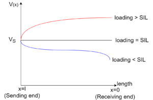
When the loading of the line is equal to the surge impedance loading, then the sending end voltage equals the receiving end voltage, and no reactive power flows in the line. In addition to this, with the line loading being greater than the surge impedance loading, the receiving end voltage is greater than the sending end voltage. In this case, the reactive power flows from the sending end to the receiving end. Finally, when the line loading is less than the surge impedance loading of the line, then the sending end voltage is greater than the receiving end voltage. Here, the reactive power flows from the sending end to the receiving end of the transmission line.
Is reactive power flow actually zero during surge impedance loading?
During the surge impedance loading of the line, whatever reactive power losses take place in the series reactance of the line. This reactive power is compensated for or produced by the shunt capacitance of the line, and the net reactive power flow in the line is zero.
The table below shows surge impedance and SIL for various voltage levels.
| $V_{rated}$ (kV) | $Z_0$ Ω | $SIL = \frac{V_{rated}^2} {Z_0}$ (MW) |
|---|---|---|
| 230 | 380 | 140 |
| 345 | 285 | 420 |
| 500 | 250 | 1000 |
| 765 | 257 | 2280 |
The voltage versus length curve shows the voltage profile for loading the line in different conditions.
- If the line loading is equal to the surge impedance loading (SIL), the voltage profile of the line is flat.
- If the line loading is greater than the surge impedance loading, then the line has an inductive nature.
- If the line loading is less than the surge impedance loading, then the line has a capacitive nature.
Reducing Surge Impedance Loading of Line
The maximum power transfer capacity of a line can be increased by decreasing the surge impedance of the line. In other words, the surge impedance loading of the line increases with the decrease in surge impedance of the line. The surge impedance of the line cannot be reduced as much by varying the spacing of the conductors. As the spacing between the conductors is mainly governed by the system voltage. However, there are some other methods to reduce the surge impedance ($Z_o$) of the line, as stated below.
Using Series Capacitor
For a loss-less line with the attenuation zero ($\alpha = 0$), the propagation constant $\gamma$ is
\[=j\omega \sqrt{LC} = j \beta\]
By using a series capacitor, the phase constant (β) reduces due to a reduction in line inductance (L). This in turn reduces the surge impedance of the line and it causes subsequent increase in the surge impedance loading of the line. Further, the use of series capacitors increases the system stability limit. However, during short-circuit conditions, it causes difficulties. Nevertheless, the capacitor also helps in reducing line voltage drops and voltage variations.
Using Shunt Capacitor
The mathematical expression for surge impedance of the line is
\[Z_0 = \sqrt{\frac{L}{C}}\]
By using a shunt capacitor, the surge impedance $Z_0$ decreases and the surge impedance loading of the line increases. But there is an increase in the phase constant (β) as the value of C increases. When synchronous machines are used, this causes load stability to worsen. Hence, on long transmission lines where stability limits are present, we cannot use this method.
More related contents:
Unsymmetrical Faults in Power System
Current Limiting Reactor
Circuit Breaker
Surge Impedance
Analysis of Symmetrical Faults in Power System
Pingback: What is Surge Impedance Loading (SIL)? - Power System Pulse - Surge Impedance
Pingback: Analysis of Symmetrical Faults - Power System Pulse